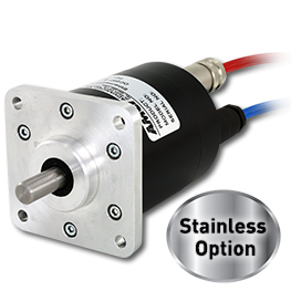
NR25 Networked Absolute Rotary Shaft Encoder


Downloads
User Manuals & Drawings
Sample Programs
NR25 EtherNet/IP RSLogix 5000 sample programs
NR25 EtherNet/IP Micro850 sample programs
NR25 DeviceNet sample programs
Configuration Files
Software
EtherNet configuration software
Description
NR25 Networked Encoders
The AMCI NR25 series of heavy-duty Networked Encoders are compatible with all PLCs/PACs that support EtherNet/IP, Modbus-TCP, DeviceNet, or Profibus. The NR25 series networked encoders are available in absolute single-turn and multi-turn packages using an IP67 rated 2.5" size industrial housing. Solid shaft and hub shaft styles are available to suit various mounting requirements. These networked absolute rotary encoders provide up to 30 bit total resolution, delivering 16 bit (65536 steps) per revolution and up to an additional 14 bit (16384 revolutions) for multi-turn versions.
Easy To Configure & Install
AMCI's networked encoders are designed for simple set-up and trouble free performance. The NR25 networked encoders are compatible with all PLCs and PACs that support EtherNet/IP, Modbus-TCP, DeviceNet, or Profibus including Allen-Bradley and Schneider. Programmed using the PLC/PAC resident software ensures hassle free integration with your application.
The NR25 networked encoders offer a variety of programmable features:
- Selectable Resolution
- Selectable Count Direction
- Selectable Velocity Format
- Programmable Presets for Zeroing or Homing
All programmable parameters and the preset offset are stored in the internal non-volatile memory for speedy retrieval, making it quick and easy to configure your NR25 networked encoder.
Heavy-duty Performance & Reliability
The NR25 networked encoder is resolver based and supplies absolute position feedback without glass discs or sensitive LED components, enabling it to withstand high levels of shock and vibration. The IP67 rated housing guarantees protection against dust and water ingress. Add the NR25 EtherNet/IP encoder's impressive shaft load ratings and ruggedness is second to none.
AMCI's NR25 networked encoder is the heavy-duty solution for single-turn and multi-turn position applications requiring serious reliability for today's harshest industrial environments.
Power over Ethernet (PoE)
AMCI's NR25 EtherNet/IP encoders come standard with Power over Ethernet (PoE), making it possible to install this encoder using a single Ethernet cable that transmits data AND power over the transmit and receive pairs (mode A)! Your connector and cabling requirements are cut in half, plus installation is simpler and less expensive. The Power over Ethernet feature allows you to use AMCI's NR25 encoder in applications where utilizing a traditional DC power supply would be inconvenient, plus all of these advantages:
- NR25 only requires a single Ethernet cable for power/data transmission (mode A)
- NR25 placement is flexible, and no longer limited to nearby power sources
- NR25 can be easily moved to wherever there is LAN cabling
- NR25 and a UPS can guarantee up time during main failures
- NR25 can be shut down or reset remotely
- NR25 requires little configuration or management
NOTE:
NR25 end connector units allow customers to either use separate network and auxiliary power connections, or a single Ethernet cable/connection to transmit data and power using Power over Ethernet (PoE).
NR25 side connector units are only available with Power over Ethernet (PoE), using a single Ethernet cable to transmit data and power.
Available Versions
NR25 (all networks): 16 bit Single-turn
Price | $969 - $1,115/ea
NR25 (all networks): 28 bit Multi-turn
Price | $1,205 - $1,351/ea
NR25 (all networks): 30 bit Multi-turn
Price | $1,336 - $1,482/ea
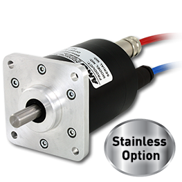
Stainless Steel Option: add to above pricing
Price | $550/ea
Note: Pricing is US Domestic only
Consult the factory for availability
Contact SalesNR25 Features
- Built-in network interface for variety of networks
- EtherNet/IP interface option offers PoE (Power over Ethernet)
- Single-turn Resolution up to 16 bit (65,536 counts)
- Multi-turn resolution up to 30 bit (65,536 counts x 16,384 revolutions)
- Programmable resolution, count direction, velocity format, & position prest
- Time Stamp
- Resolver-based durability
- IP67 Ingress Protection Rating
- Solid shaft and hub shaft versions
- ODVA compliant
- Compatible w/ any PLC supporting EtherNet/IP, Modbus-TCP, Profibus, or DeviceNet networks, including Allen-Bradley + Schneider PLCs
The Best PLC Integration Available
AMCI products are uniquely designed to provide the best PLC integration available. Unlike other products that require a separate software package for configuration or operation, AMCI's PLC-based products are programmed using your PLC's software - nothing new to buy or learn!
Our expertise with the leading PLC manufacturers (e.g. Allen-Bradley Schneider, GE, etc) is unmatched when it comes to high performance Specialty I/O, Position Sensing, and Motion Control technology.
Compatible Networks
AMCI's NR25 Series is compatible with any PLC that supports these networks
Heavy-Duty Reliability
The AMCI NR Series encoders are engineered to save customers time and money. They are resolver-based, providing the heaviest duty 2.5" rotary shaft encoder available, anywhere. Utilizing this innovative design, these optical encoder replacements deliver reliable, heavy-duty position feedback. Several features set this family of networked rotary encoders apart from the competition; namely, its cost saving durability, field programmability, and wide range of applications.
- Cost-saving durability
- Resolver-based reliability
- Field programmable output resolution
- Wide range of applications
- More...
Want to learn more?
Specifications
Mechanical Specifications
| NR25 Networked Absolute Rotary Shaft Encoder | |
|---|---|
| Package style: | 2.5" diameter housing available with flange, servo, or hub shaft mounting |
| Housing: | Powder coated aluminum housing or stainless steel |
| Shaft sizes: | Solid shaft diameter 1/4" , 3/8", 5/8”, or 10 mm diameter stainless steel Hub shaft inner diameter 1/2” standard inner diameter stainless steel shaft 3/8", 1/2", 10mm, and 12mm bore reducers |
| Shaft loading: | Solid shaft: 1/4", 3/8", and 10mm shafts: 40 lbs. radial/20 lbs. axial maximum shaft loading. Bearing life rated at 2X10⁹ revolutions minimum at maximum shaft load. 5/8" shaft: 100 lbs. radial/50 lbs. axial maximum shaft loading. Bearing life rated at 2X10⁹ revolutions minimum at maximum shaft load. Hub shaft: 3/8", 1/2", 10mm, and 12mm shafts: 40 lbs. radial/20 lbs. axial maximum shaft loading. Bearing life rated at 2X10⁹ revolutions minimum at maximum shaft load. |
| Starting Torque: | Solid shaft: 1/4”, 3/8”, & 10mm shafts = 2.0 oz-in max @25° C 5/8” shaft = 6.0 oz-in max @25° C Hub shaft: 3/8", 1/2", 10mm, and 12mm shafts = 6.0 oz-in max @25° C |
| Moment of inertia: | Solid shaft: 1/4", 3/8", & 10 mm shafts = 6.00 x 10⁻⁴ oz-in-sec2 5/8" shaft = 8.50 x 10⁻⁴ oz-in-sec2 Hub shaft: 3/8", 1/2", 10mm, and 12mm shafts = 7.00 x 10⁻⁴ oz-in-sec2 |
| Connector location: | --EtherNet/IP & Modbus-TCP-- End connector version: 2 connectors (1 connector) for data or data/power when using Power over Ethernet (PoE) (1 connector) for auxiliary power if not using PoE feature Side connector version: 1 connector - PoE ONLY (mode A) (1 connector) transmits data and power via Power over Ethernet (PoE) --Profibus-- End connector version: 3 connectors (1 connector) for power (1 connector) BUS IN (1 connector) BUS OUT --DeviceNet-- End connector version: 2 connectors (1 connector) BUS IN & power (1 connector) BUS OUT & power |
Connectors Pinouts: Ethernet/IP & Modbus-TCP
Power Connector
| Pin | Signal | Explanation |
| 1 | No Connection | - |
| 2 | +Vdc | 12 to 54Vdc |
| 3 | No Connection | - |
| 4 | Common | - |
| Pin | Signal | Explanation |
| 1 | No Connection | - |
| 2 | +Vdc | 12 to 54Vdc |
| 3 | No Connection | - |
| 4 | Common | - |
Data/PoE Connector
| Pin | Signal | 568A Color | 568B Color |
| 1 | Tx+ | White / Green Tracer | White / Orange Tracer |
| 2 | Rx+ | White / Orange Tracer | White / Green |
| 3 | Tx- | Solid Green | Solid Orange |
| 4 | RX- | Solid Orange | Solid Green |
| Pin | Signal | 568A Color | 568B Color |
| 1 | Tx+ | White / Green Tracer | White / Orange Tracer |
| 2 | Rx+ | White / Orange Tracer | White / Green |
| 3 | Tx- | Solid Green | Solid Orange |
| 4 | RX- | Solid Orange | Solid Green |
Connectors Pinouts: profibus
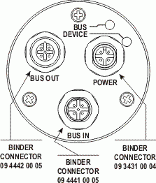
CON1 Power Connector
Standard A-coded 4-pin M12 male connector
(e.g. Binder P/N 09-3431-00-04)
| Pin | Signal |
| 1 | +24Vdc (10 to 30Vdc) |
| 2 | No Connection |
| 3 | DC Common |
| 4 | No Connection |
| Pin | Signal |
| 1 | +24Vdc (10 to 30Vdc) |
| 2 | No Connection |
| 3 | DC Common |
| 4 | No Connection |
CON2 BUS OUT Data Connector
Standard B-coded 5-pin M12 female connector
(e.g. Binder P/N 09-4442-00-05 or Phoenix P/N 1515044)
| Pin | Signal |
| 1 | BUS_VDC isolated |
| 2 | BUS-A line (green) RxD/TxD-N |
| 3 | BUS_GND isolated |
| 4 | BUS-B line (red) RxD/TxD-P |
| 5 | No Connection |
| Pin | Signal |
| 1 | BUS_VDC isolated |
| 2 | BUS-A line (green) RxD/TxD-N |
| 3 | BUS_GND isolated |
| 4 | BUS-B line (red) RxD/TxD-P |
| 5 | No Connection |
CON3 BUS IN Data Connector
Standard B-coded 5-pin M12 male connector
(e.g. Binder P/N 09-4441-00-05)
| Pin | Signal |
| 1 | No Connection |
| 2 | BUS-A line (green) RxD/TxD-N |
| 3 | No Connection |
| 4 | BUS-B line (red) RxD/TxD-P |
| 5 | No Connection |
| Pin | Signal |
| 1 | No Connection |
| 2 | BUS-A line (green) RxD/TxD-N |
| 3 | No Connection |
| 4 | BUS-B line (red) RxD/TxD-P |
| 5 | No Connection |
Connectors Pinouts: DeviceNet
BUS IN
| Pin | Signal | Explanation |
| 1 | See Note 1 | Shield Drain |
| 2 | +Voltage | Red |
| 3 | -Voltage | Black |
| 4 | CAN_H | White |
| 5 | CAN_L | Blue |
| Pin | Signal | Explanation |
| 1 | See Note 1 | Shield Drain |
| 2 | +Voltage | Red |
| 3 | -Voltage | Black |
| 4 | CAN_H | White |
| 5 | CAN_L | Blue |
BUS OUT
| Pin | Signal | Explanation |
| 1 | See Note 1 | Shield Drain |
| 2 | +Voltage | Red |
| 3 | -Voltage | Black |
| 4 | CAN_H | White |
| 5 | CAN_L | Blue |
| Pin | Signal | Explanation |
| 1 | See Note 1 | Shield Drain |
| 2 | +Voltage | Red |
| 3 | -Voltage | Black |
| 4 | CAN_H | White |
| 5 | CAN_L | Blue |
NOTE #1) Pin 1 on the Bus In and Bus Out connectors are internally connected to each other and are connected to the body of the NR25 through a 2 nF capacitor.
ENVIRONMENTAL SPECIFICATIONS
| NR25 Networked Absolute Rotary Shaft Encoder | |
|---|---|
| Enclosure: | IP67 (valid only with working shaft seal & mating connector fitted) |
| Shock: | 50 G's for 11 mSec |
| Vibration: | 20 g, 5 to 2,000 Hz |
| Operating temperature: | -40° C to 85° C standard |
ENVIRONMENTAL SPECIFICATIONS
| NR25 Networked Absolute Rotary Shaft Encoder | |
|---|---|
| Enclosure: | IP67 (valid only with working shaft seal & mating connector fitted) |
| Shock: | 50 G's for 11 mSec |
| Vibration: | 20 g, 5 to 2,000 Hz |
| Operating temperature: | -40° C to 85° C standard |
Electrical Specifications
| NR25 Networked Absolute Rotary Shaft Encoder | |
|---|---|
| Output Code: | EtherNet/IP, Modbus-TCP, Profibus-DP, or DeviceNet |
| Resolution: | Single Turn = 65536 counts max Multi Turn = (2 versions) 65536 counts / turn & 4096 turns maximum 65536 counts / turn & 16384 turns maximum |
| Direction of Increasing Counts: | Programmable over the network default = CW increasing looking at the shaft |
| Programmable Parameters: | -Direction of Increasing Counts -Counts Per Turn -Velocity Units -Preset Function -Total Measurement Range (defines the number of counts where the position rolls over to zero) |
| Time Stamp: | Optional input data that replaces the Velocity. Time stamp is an unsigned double integer value with an interval of 400 nanoseconds; rolls over every 1717.9869184 seconds. |
| Power requirements (including PoE): | --EtherNet/IP & Modbus-TCP-- 12 to 54Vdc 2.5 W maximum 100mA @ 24Vdc --Profibus-DP-- 10 to 30Vdc 1.32 W maximum 55mA @ 24Vdc --DeviceNet-- 11 to 25Vdc 1.5 W maximum 50mA @ 24Vdc |
Electrical Specifications
| NR25 Networked Absolute Rotary Shaft Encoder | |
|---|---|
| Output Code: | EtherNet/IP, Modbus-TCP, Profibus-DP, or DeviceNet |
| Resolution: | Single Turn = 65536 counts max Multi Turn = (2 versions) 65536 counts / turn & 4096 turns maximum 65536 counts / turn & 16384 turns maximum |
| Direction of Increasing Counts: | Programmable over the network default = CW increasing looking at the shaft |
| Programmable Parameters: | -Direction of Increasing Counts -Counts Per Turn -Velocity Units -Preset Function -Total Measurement Range (defines the number of counts where the position rolls over to zero) |
| Time Stamp: | Optional input data that replaces the Velocity. Time stamp is an unsigned double integer value with an interval of 400 nanoseconds; rolls over every 1717.9869184 seconds. |
| Power requirements (including PoE): | --EtherNet/IP & Modbus-TCP-- 12 to 54Vdc 2.5 W maximum 100mA @ 24Vdc --Profibus-DP-- 10 to 30Vdc 1.32 W maximum 55mA @ 24Vdc --DeviceNet-- 11 to 25Vdc 1.5 W maximum 50mA @ 24Vdc |
Compatible Cables & Connectors
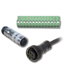
The following mating connectors are available from AMCI
- Note that any commercially available M12 connectors with the proper coding and contacts can be used
Power Connectors (Sold Separately)
| --- EtherNet/IP, Modbus-TCP, Profibus-DP --- | |
| Power Mating Connector (AMCI Part# MS-29) | Standard M12 4 pin female straight connector such as Binder #99-0430- 12-04 or equivalent. (sold separately) Standard M12 4 pin female right angle connector such as Binder #99-0430- 52-04 or equivalent (sold separately) |
Data Connectors (Sold Separately)
| --- EtherNet/IP & Modbus-TCP (Data/PoE) --- | |
| Mating Connector (AMCI Part# MS-28) | Standard M12 D-coded 4 pin male connector such as Binder #99-3729- 810-04 or equivalent (sold separately) |
| --- Profubus-DP --- | |
| BUS OUT Connector (AMCI Part# MS-39) | Standard B-coded 5-pin M12 male straight connector such as Binder P/N 99-0437- 105-05 (sold separately) Standard B-coded 5-pin M12 male right angle connector such as Binder P/N 99-0437- 145-05 (sold separately) |
| BUS IN Connector (AMCI Part# MS-38) | Standard B-coded 5-pin M12 female straight connector such as Binder P/N 99-0436- 110-05 (sold separately) Standard B-coded 5-pin M12 female right angle connector such as Binder P/N 99-0436- 165-05 (sold separately) |
| --- DeviceNet --- | |
| BUS IN Connector (AMCI part #MS-31) | Standard M12 A-coded 5 pin female straight connector such as Binder #99-0436- 12-05 or equivalent (sold separately) Standard M12 A-coded 5 pin female right angle connector such as Binder #99-0436- 52-05 or equivalent (sold separately) |
| BUT OUT Connector (AMCI part #MS-32) | Standard M12 A-coded 5 pin male straight connector such as Binder #99-0437- 12-05 or equivalent (sold separately) Standard M12 A-coded 5 pin male right angle connector such as Binder #99-0437- 52-05 or equivalent (sold separately) |
Compatible Cord Sets / Cables (Sold Separately)
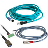
| Data Cord Sets: | -- - EtherNet/IP & Modbus-TCP AMCI Cordset part #CNER-5M (5 meter cable, M12 and RJ45 connectors) Phoenix #1569391, #1569401, #1569414, #1569427, or equivalent. (sold separately) -- - DeviceNet & Profibus DP-- - Can be purchased from the following manufacturers: Phoenix Contact: www.phoenixcontact.com Turck Inc: www.turck-usa.com Lumberg Automation: www.lumberg-automationusa.com |
| Power Cord Sets: | -- - EtherNet/IP & Modbus-TCP, Profibus-DP -- - AMCI Cordset part #CNVL-2M (2 meter cable, M12 connector and flying leads) Phoenix #1536308 or equivalent (sold separately) |
| Cables: | -- - DeviceNet & Profibus DP -- - Can be purchased from the following manufacturers: Belden Inc: www.belden.com Phoenix Contact: www.phoenixcontact.com |
Video
NR Series Networked Rotary Encoders
Compatible with all PLCs that support EtherNet/IP, DeviceNet, Modbus-TCP, or Profibus-DP, these networked rotary sensors are available in single-turn and multi-turn versions.
Duration 02:22
Technical Drawings
EtherNet/IP & Modbus TCP Version Drawings
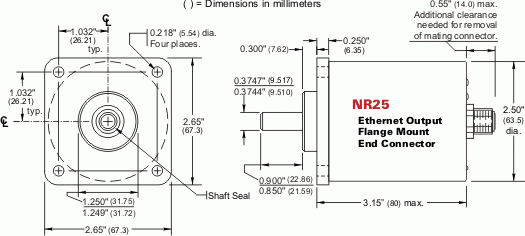
NR25 = EtherNet/IP & Modbus TCP Single-turn and Multi-turn, Flange Mount, End Connector
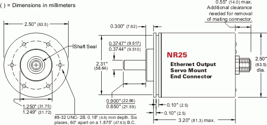
NR25 = EtherNet/IP & Modbus TCP Single-turn and Multi-turn, Servo Mount, End Connector
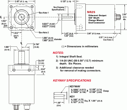
NR25 = EtherNet/IP & Modbus TCP Single-turn and Multi-turn, 5/8" Shaft, Flange Mount, End Connector
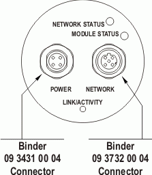
NR25 = EtherNet/IP & Modbus TCP Single-turn and Multi-turn: End View
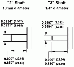
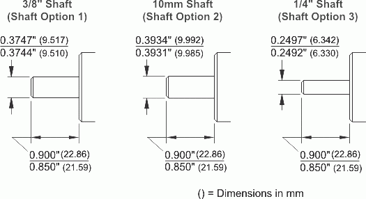
NR25 = EtherNet/IP & Modbus TCP Single-turn and Multi-turn: Alternate Shafts
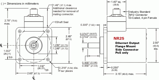
NR25 = EtherNet/IP & Modbus TCP Single-turn and Multi-turn, Flange Mount, Side Connector
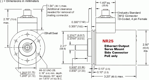
NR25 = EtherNet/IP & Modbus TCP Single-turn and Multi-turn, Servo Mount, Side Connector
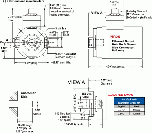
NR25 = EtherNet/IP & Modbus TCP Single-turn and Multi-turn, Hub Shaft Mount, End Connector
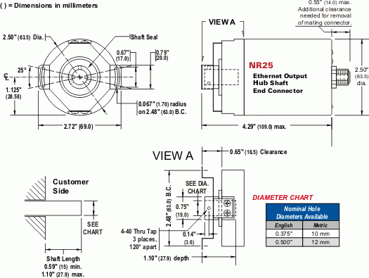
NR25 = EtherNet/IP & Modbus TCP Single-turn and Multi-turn, Hub Shaft Mount, Side Connector
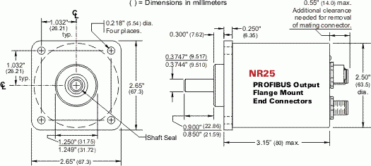
NR25 = Profibus-DP Multi-turn, Flange Mount, End Connector
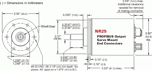
NR25 = Profibus-DP Multi-turn, Servo Mount, End Connector
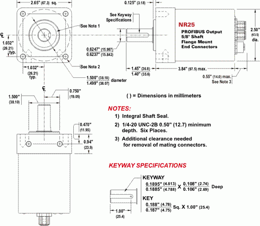
NR25 = Profibus-DP Multi-turn, 5/8" Shaft, Flange Mount, End Connector
NR25 = Profibus-DP Multi-turn, Hub Shaft Mount, End Connector
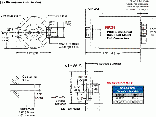
NR25 = Profibus-DP Multi-turn: End View
NR25 = Profibus-DP Multi-turn: Alternate Shafts

NR25 = DeviceNet Single-turn and Multi-turn, Flange Mount, End Connector
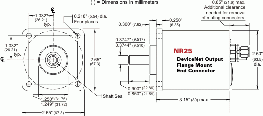
NR25 = DeviceNet Single-turn and Multi-turn, Servo Mount, End Connector
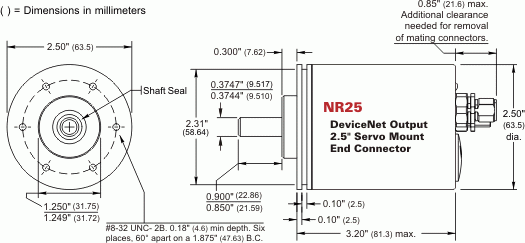
NR25 = DeviceNet Single-turn and Multi-turn, 58mm Servo Mount, End Connector
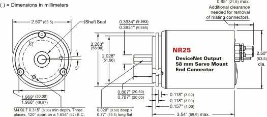
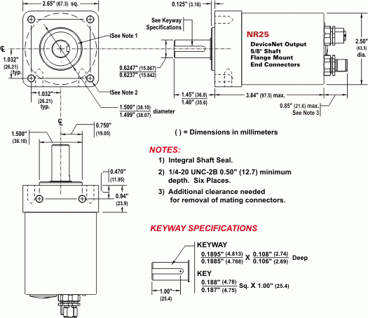
NR25 = DeviceNet Single-turn and Multi-turn, 5/8" Shaft, Flange Mount, End Connector
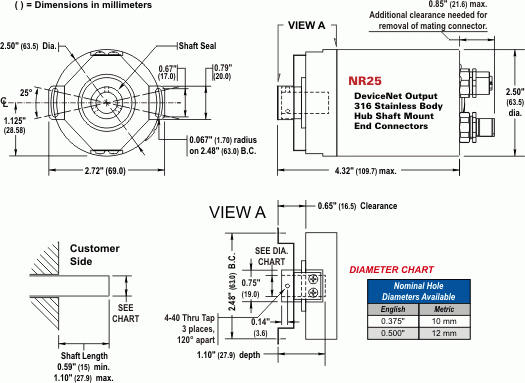
NR25 = DeviceNet Single-turn and Multi-turn, Hub Shaft Mount, End Connector
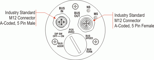
NR25 = DeviceNet Single-turn and Multi-turn: End View
NR25 = DeviceNet Single-turn and Multi-turn: Alternate Shafts
AMCI makes buying PLC-based automation easy...our sales group will help you:
- Select the right product for your application
- Pay by credit card using your Visa, Mastercard, Discover, or American Express
- Coordinate alternative payment methods (P.O., wire transfers, etc.)
- Locate a distributor convenient to your region of the country

Contact AMCI Sales today:
860-585-1254
Ordering Information

AMCI's sales team takes the hassle out of placing your order. We'll advise on product selection, alternatives, lead times, and present you with point of purchase options. Call (860) 585-1254 or email AMCI sales today!
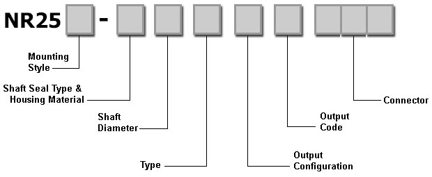
create your part number
Generate your NR25 series networked rotary shaft encoder part number by using this helpful ordering guide. Starting from left to right, use the following diagram and table to choose the desired options. Each gray box must contain a single alphanumeric character. Please note the following…
| Part Number Character | NR25 Networked Absolute Multi-turn Encoder | Most Popular Selections |
|---|---|---|
| Mounting style: | F = 2.65" square flange S = 2.5" diameter servo mount (unavailable w/ the 5/8” shaft option) H = Hub shaft | F (Square flange) |
| Shaft Seal Type & Housing Material: | A=Nitrile seal, stainless steel housing B=Nitrile seal, aluminum housing C=Viton seal, stainless steel housing V=Viton seal, aluminum housing | B (Nitrile seal) |
| Shaft Diamter: (must choose either solid or hub shaft) | Solid shaft option (Flange mount only) 1 = 3/8" diameter 0.875” length, No Flat 2 = 10mm diameter 0.875” length, No Flat 3 = 1/4" diameter 0.875” length, No Flat 4 = 6mm diameter 10mm length, w/Flat 5 = 5/8" diameter 1.30” length, w/Keyway 6 = 10mm diameter 20mm length, w/Flat --- Hub shaft option 1 = 3/8" inner diameter 1.1” max. depth 2 = 10mm inner diameter 1.1” max. depth 4 = 1/2" inner diameter 1.1” max. depth 6 = 12mm inner diameter 1.1” max. depth | 1 (3/8" shaft) --or-- 4 (1/2" inner diameter) |
| Interface Type: | E = Ethernet interface (EtherNet/IP & Modbus TCP) B = Serial interface (Profibus or DeviceNet) | E, B Both types readily available |
| Output Configuration: | 1 = 16 Bit Single Turn (65536 counts/turn) 2 = 28 Bit Multi Turn (65536 counts/turn & 4,096 turns) 3 = 30 Bit Multi Turn (65536 counts/turn & 16384 turns) | 2 (Multi-turn) |
| Output Code: | A = EtherNet/IP P = Profibus-DP D = DeviceNet | A, P, D All types readily available |
| Connector Location: | --Ethernet interface-- E04 = End (2 connectors) 1 connector for data or data/power (Power over Ethernet - PoE) 1 connector for auxiliary power if not using PoE feature S02 = Side (1 connector) 1 connector transmits data and power via Power over Ethernet (PoE) --Profibus interface-- E04 = End (3 connectors) 1 connector for bus in 1 connector for bus out 1 connector for aux power --DeviceNet-- E02 = End (2 connectors) each connector supplies data & power E01 = End (1 connector) 1 connector supplies data & power | E04 (End Connector) --DeviceNet-- E02 |
Resources
NR25 Product Sheet
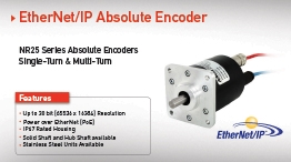
NR25 Networked Rotary Encoder - Single-turn & Multi-turn absolute encoders up to 30 bit res...
PDF DownloadResolver-Based?
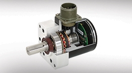
Resolver-based Rotary Shaft Encoders provide the heaviest duty 2.5" rotary shaft encoder availa...
Read the TutorialWebinar

Programming AMCI EtherNet/IP Motion Products with RSLogix/Studio 5000: This 30 minute webinar a...
Watch Now

